Journal of the British Interplanetary Society, Vol. 38, pp.
305-314~1985.
AN EVOLUTIONARY SPACE STATION
ARCHITECTURE
O.P. HARWOOD
Huntington Beach, California,
USA.
------------------------------------------------------------------------------------------------------------------------------------------------
A
space station, an investment in permanent space occupancy, is justifiably
concerned with evolutionary growth, adaptability and interchangeability. The
system proposed here for its construction is based on the premise that whatever
configuration is first launched will be found less satisfactory than envisaged
in ground-based studies. At this point, rearrangement would be preferable to
starting all over again.
To assure construction of any shape (or any
size) of assembly, the system is a trusswork of equal-length bars, habitable
modules interchangeable with struts. There are six standard units and no
adapters. The key element is a nodal sphere made from 12 identical
sub-assemblies, each corresponding to a face of a bulged rhombic dodecahedron.
Each port includes a berthing mechanism that allows lateral
engagement.
Habitable modules are integrally stiffened shells with
standard patterns of attachment fittings for equipment installation, an
extension of the concept that transformed a Saturn S-IVB stage into the Orbital
Workshop of Skylab.
External appendages (antennae, solar arrays, etc.)
plug into ports in the nodes at the assembly's edges, while hangar spaces are
multi-cell volumes inherent in the lattice. Clocking and identification of the
port interfaces assure correct assembly.
Not an alternate configuration,
the construction system could build any of
them.
------------------------------------------------------------------------------------------------------------------------------------------------
1. ~ INTRODUCTION
The Space Station will differ from previous space
programmes by being not only re-usable but continuously in use. Since it will be
revisited regularly and can therefore be frequently up-dated, it does not
require advanced and risky technology at the outset. However, it must inherently
possess adaptability for new technology as it develops. It is imperative that
this capability be achieved without rebuilding the basic framework. This means
that initial priority should be given to mounting provisions, distributive
systems, standard interfaces and basic geometry.
This paper offers a
system designed to meet these specifications. Not intended as an alternative to
any Space Station configuration, it is a means to constructing any of them and,
if necessary, converting from one to another. Developed initially as a set of
modules for long-duration Shuttle Orbiters, the system was expanded to "evolve"
into an embryo Space Station. Attention has therefore been focused on general
construction rather than specific forms.
Earth-bound activities such as
cutting, drilling and trimming produce chips that are swept up and discarded
after falling to the floor. In space, they produce floating clouds of dangerous
debris. Similarly, loose bolts, nuts and washers, if lost, threaten the reliable
operation of machinery. Clearly, standardized, pre-installed attachment
provisions and captive fasteners must be emphasized.
Skylab experience
offers precedents for such standardization. The walls and partitions built into
an S-IVB hydrogen tank to make an Orbital Workshop were made of open lattice
grid, a regular pattern of nodes 107 mm apart at the intersections of bars
forming equilateral triangles. The construction was open to drain hydrogen fuel,
since it was originally intended to function as a working stage. The triangular
form was necessary for carrying shear loads across an open trusswork. Figure 1
shows a typical installation of equipment and the S-IVB that was modified to
house the living and laboratory quarters. It is evident that any installation on
this standard "pegboard" could be removed and replaced by any other equipment
designed to fit the pattern without the cost and delays from negotiating changes
in a structure designed without these accommodations.
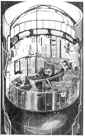 Fig. 1. The Skylab
Orbital Workshop, showing the grid floor.
The whole habitable
frame and associated equipment (about 17.,000 kg) was suspended from the
waffle-stiffened S-IVB cylinder. Fortuitously, this structure contained about
2,000 attachment opportunities at the intersections of stiffening ribs. These
were exploited by installing a stud in a tapped hole at these locations (Fig.
2).
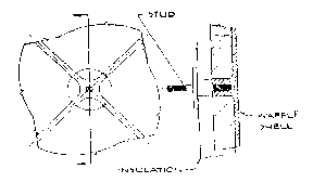
Fig.
2 Standard stud in S-IVB tank waffle node
In this case, the
tapping operation was a pre-launch rework; for a space station, such provisions
must be designed in at the start. The discovery of inherent accommodations
accidentally offered by the structural arrangement was, in Skylab, followed by
intentional inclusion of similar capability in the added structure. If Skylab
had not fallen out of orbit before it could be re-boosted, it would even now be
able to accept new equipment in exchange for the old. For the Space Station,
better initial planning should provide even more versatility.
It is
obvious that the growth and adaptability so desired in the installed subsystems
must also be a prominent and planned feature of the subsystem that supports all
of them: the structure. In fact, it should start there. Structure, in this
sense, connotes "architecture" and all that implies: space allocation,
protection, accessibility and maintainability, along with its more obvious role
as a sustainer of loads.
In response to this compelling logic, the system
here proposed for space stations:
• Is not an alternate configuration: it
implements any of them
• Can fill all of space - or any part of It
• Has elements sized by the Shuttle payload bay
• Is structurally
efficient, its growth and controllability not being limited by low natural
frequency
• Uses only six base construction units with standard
interfaces and component mounting provisions.
• Considers pressurized modules and construction struts interchangeable parts of a common
lattice
• Permits evolutionary growth, shrinkage and reconstruction in
another form after initial operation
• Requires little new technology at
the start but can accommodate any that develops later
To summarize, this
system is not only "technology transparent,' as requested, it can also be called
"configuration transparent."
2. GEOMETRIC CONSIDERATIONS
If a
large space lattice is to be truly versatile it must be able to assume any
shape. To do this, it must consist of identical cells or cell groups endlessly
repeatable. If the edges of such cells are equal-length elements (a desirable
condition of standardization), two basic systems are derived:
• Cubic:
square faces and corners
• Tetrahedral: equilateral triangles
Both
forms can be modeled three-dimensionally, as shown in Fig. 3.
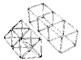
Fig. 3 Models of
cubic and tetrahedral space trusses
To explain space networks
in a two-dimensional manner, square and triangular area arrays are depicted in
Fig. 4.
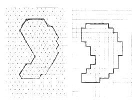 Fig.
4 . Approximations of an arbitrary shape with square and triangular
networks
The small patches shown can be expanded infinitely,
if necessary. Their three-dimensional equivalents are cubic and tetrahedral
lattices. The latter is somewhat misnamed because space cannot be filled with
tetrahedrons. Bars running in the same six directions as the edges of a
tetrahedron divide space into tetrahedrons and octahedrons in the ratio of two
to one. However, the nodes are all identical; 12 bars converge at each
intersection.
As indicated, an arbitrary shape can be approximated with
either array, though the triangular one, running in three directions instead of
two, can more closely approximate the slope of the figure's outline.
For
any large space structure, the Space Station included, the tetrahedral truss is
structurally superior to the cubic form because triangles are inherently rigid
and stable. A cubic lattice is made stable by adding diagonal struts or cables,
thereby creating triangles; but in this case the lengths are different. So, for
a cellular system or a crystalline lattice, the rational choice is tetrahedral,
both for large frames and for clusters of habitable modules. Inconsistency of
geometric arrangement implies sets of cost-incurring adapters.
The
apparent popularity of cubic cells may stem from a universal understanding of
the geometry at an intersection. It is also obvious that the polyhedron that
presents a face normal to each of the lattice bars is a cube. It has not often
been recognized that a pressurized node with no preferential directions of
strength (as in an infinite lattice) needs to be a sphere divided into six
identical bulged patches, the projections of a cube face on a surrounding
sphere. Instead, most airlocks have been cylinders, or intersections of
them.
What has rarely been recognized is that for a tetrahedral lattice
there is also a polyhedron with a face normal to each incoming bar on which an
interface can be centered. Figure 5 shows some polyhedral subdivision of
spheres.
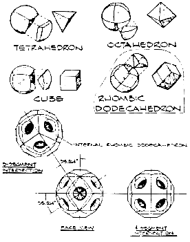
Fig. 5. Polyhedral subdivisions of spheres and a spherical node for a
tetrahedral lattice.
The cubic version has already been
mentioned. The form of interest for the tetrahedral lattice is the rhombic
dodecahedron. Not generally known to designers of large space structures, it is
well enough known to students of polyhedrons to have been given the name it
bears. In a close hexagonal packing of spheres in space, where 12 spheres are in
contact with a central one while touching each other, the planes of tangency at
the points of contact around the central sphere are the faces of a rhombic
dodecahedron. It, like the cube, when packed against others of its kind,
completely fills space without voids. This seems to be a necessary
characteristic for the node of a universal space-filling lattice. The literature
indicates that this polyhedron and the cube are the only two with identical
faces that possess this property.
A model of this shape at a tetrahedral nodal intersection is shown in Fig. 6.
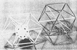
Fig. 6.
Model of a rhombic dodecahedron at a tetrahedral lattice
node.
It is the key element in an endlessly repeating lattice
system which, by its ability to fill all of space, can also fill any part of it.
Thereby, it permits the construction of any space station configuration or, for
that matter, an assembly to carry explorers to the vicinity of Mars.
The
foregoing discussion treated nodes in the lattice as a given condition, although
the existence of such units has been the subject of debate concerning the
question of affordability. Without any formal economic analysis, this
uncertainty should be settled by rational discussion. Firstly, a node should be
expected to function as an airlock and a space station without airlocks is
unthinkable. In addition, even the simplest two-dimensional array (the square
one shown in Fig. 4) has intersections where four bars meet. Each bar has two
end connections. Therefore, to come out even, the infinite array must have twice
as many bars as junctions. The triangular array has three times as many bars as
intersections, and a three-dimensional tetrahedral lattice requires six times as
many bars (or modules) as nodes. Therefore, for universal adaptability, nodes
cannot be integral with bars because the required numbers of each are
diflferent. Growth would be restricted and more nodes (or the equivalent) would
be procured than are required.
3. APPLYING THE CONSTRUCTION
SYSTEM
The Space Station depicted in Fig. 7 is the initial all-up
configuration of the so-called "power tower."
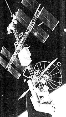
Fig. 7. Space
Station study reference configuration, the "power tower."
This
design is the reference for the definition phase Space Station studies. It
features a deployable structural main frame that links appendages such as
power-generating arrays, experiments, hangars, antennae and habitable modules.
The external size differences between initial and growth versions is small.
Chiefly, the power-generating systems switch from solar cells to heat-cycle
turbines, the number of pressurized modules increases and the main frame is
reinforced with parallel beams. Increases in mass and technology state are not
matched by size or shape changes in basic architecture. Deployable mainframes do
not permit it.
The design's counterpart in the construction scheme
proposed here is shown in Fig. 8.
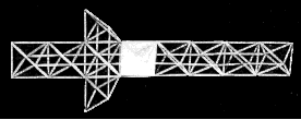
Fig. 8.
Representation of a tetrahedral "power tower"
This is a model
of the main frame; appendages are not included. While the overall arrangement is
essentially the same, there are basic detailed diflferences:
• The core
structure is erectable, not deployable, each bar representing a span of 17.76
m.
• Some of the bars - any appropriate clustered group - are habitable
modules with attendant nodal airlocks.
• Appropriately scaled up, the
assembly as shown is 134 m long with a span across the stub arms of 50.3 m. The
deployable power generating equipment extends beyond these arms, supported on
rotary bearings.
• Hangars are screen-enclosed octahedral cells of the
core, one such opportunity being shown on the model. Each hangar cell has a
volume of over 1700 m3, accessible through a triangular door (one removed side)
15 m wide by 13 m high. Probably four or five such cells are usable as hangars
in the size of assembly shown, though the core itself can be expanded
indefinitely.
• An assembly of this size and form is made from 120 bars
and 40 nodal joints, both of variable composition. In all, 240 connections must
be made after the bars are made up and transported to the assembly point. The
connections are built into the standard units with no loose parts and no adapter
brackets.
A now-discarded configuration that received considerable
early attention is the "delta" space station (Fig. 9).
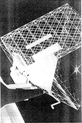
Fig. 9. "Delta"
configuration studied by NASA.
As designed, its three
deployable structural panels each contained about 1600 members, almost 5000
altogether including splices. It was designed this way "to minimise EVA" as
stated in the final report. While this statement may be true for an identical
design, one intended to be erectable would be expected to entail much fewer and
larger elements.
Figure 10 shows another model representing the "delta"
design as built with the tetrahedral truss system. 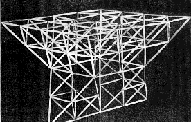 Fig 10. Tetrahedral
version of the "Delta".
As expected, while it is about 47 m
high, it uses only 147 bars and 51 nodes. As many as 10 of the bars are standard
pressurized modules, interconnected through six nodal balls; the rest consists
of standard struts and corresponding nodal fittings. Unoccupied nodal ports are
available for EVA, docking and accessory modules. As the manned portion of the
station increases in size, bars and nodal connectors can be replaced by
habitable modules and nodal airlock balls.
Solar panels on top of the
configuration are assumed to be NASA-developed fold-up panels contained in split
boxes extended by an "astromast" or the equivalent, stretching the solar blanket
between box-halves. In this case, the panels are double blankets 7.9 by 33.5 m
in size; there are 16 altogether, providing about 4250 m2 of collection area for
400 kW or more of power. The arrays do not all have to be there at the start,
nor does all the structure. Between the solar panels and the occupied modules at
the apex of the delta is a hangar space made by removing structurally
unnecessary bars from the centre; it is a large octahedron wlth 33.5 m edges.
Its volume is about 10,500 m3. Note that slices at appropriate angles through
the lattice uncover square patterns where they may be needed.
4. ELEMENTS
OF THE SYSTEM
The "meccano set" for a universal tetrahedral construction
system consists of seven basic units (six, if a habitable module is always made
in a single size). At least three of these elements make up each of the
assemblies in the configuration models. Figure 11, showing how the standard
16.76 m spacing is filled by standard units, identifies the first three
elements, as follows:
1. Nodal Airlock. This is the spherical entity
subdivided into 12 identical rhombic subassemblies that is the key to the
lattice geometry and provides ports for EVA, docking or accessories.
2.
Habitable Module Cylindrical Barrel. This is the standard shell segment for all
habitable modules: laboratories, command centers, sleeping quarters or
workshops. Each segment's length is the same as the distance across opposing
flats of the nodal ball to allow the combinations shown. The assumed diameter is
4.32 m,
3. Habitable Module Cone End. This unit closes out habitable
spaces, incorporating at its narrow end the same attachment and functional
interface as must be built into each of the 12 faces on the nodal ball. Its 60°
conical shape is determined by the equilateral triangular relationship with
adjacent units.
Where the structural frame extends beyond the inhabited
volume of a space station, the node-to-node spacing is maintained by the
remaining three standard elements:
4. Half-Strut. This unit is a tapered
structural column with androgynous connectors on both ends. Its length is half
that required to reach between structural cluster fittings at the nodes
("hedgehogs").
Fig. 11. The seven construction elements in a hypothetical
2-dimcnsional assembly.
5. Folding Tripod. All ties between pressurized
units and the open structural frame are made through this unit. Its
length is half the distance between the opposing faces of two nodal balls. It
combines with a half-strut when the elements at the nodes are
dissimilar.
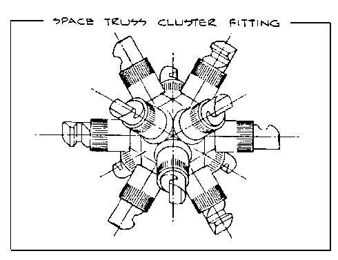
6. "Hedgehog" Cluster Fitting. This is an assembly with 12
stubs identical to the androgynous ends on assembled strut pairs. The stubs are
geometrically related in the manner of faces on airlock nodes.
7.
Pressurized Connecting Tunnel.
The system is sized by the
assumption that one Shuttle load consists of one airlock ball and one full-sized
13.4 m habitable module as shown in Fig. 12. For the start of a space station,
the first launch should probably orbit a power module complete with attitude
controls and a small propulsion system. When the following three launches bring
up three bay-filling payloads, as shown, a minimum system can become
operational. This small system could barely sustain a 2 or 3 man crew between
resupply visits but it would be a start.
The 12 port node is the
determinant of the construction when its 12 identical sub-units are properly
identified. The orientation and labeling of the faces for this purpose are
shown in Fig. 13. It starts with a 3-face patch forming the spherical projection
of a face of a tetraherdron. There are four such groups to a ball. As
illustrated, the groups are 12-3, 5-6-11, 4-7-12 and 8-9-10.
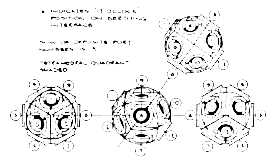
Fig. 13.
Nodal port "clocking" and identification.
Note that the
"12-o'clock" angular position of each port is pointed toward the center of the
group, most clearly shown in patch 1-2-3. When this procedure is followed for
all four patches, the opposing ports on the ball are always oriented in the same
direction. Therefore, nodal balls spatially oriented in the same manner always
correctly align with cylindrical modules whose ends are also "clocked"
alike.
Assembly alignment can be automatically assured when the polyhedral faces are numbered like cubical dice (whose opposite face numbers add up to 7),
for a 12 faced entity like this, the sum of opposite face numbers is 13. Thus,
when a habitable module end is plugged into port 5 of a ball, its opposite end
fits port 8 of the next node. The proper assembly of any space station
arrangement can be defined unambiguously in this manner.
5. NODAL AIRLOCK
BALL
In a lattice assembly of habitable modules interconnected by
spherical nodes, any nodal unit is an airlock. As such, it must be sealable to
prevent loss of the breathable atmosphere. This, in turn, leads to a requirement
for inward opening doors, one for each penetration, or 12 in the element
appropriate for tetrahedral truss geometry. In the airlock photograph shown in
Fig. 14, one of the 12 identical subunits is shown removed (at lower right).
Accessories shown plugged in include a 4-thruster propulsion unit and a
suggested battery pack.
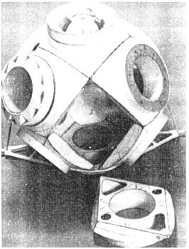
Fig. 14. Nodal
airlock ball with standard sub-assembly (lower right) and accessories - thruster
group and battery pack.
A spherical shape is indicated for
good reasons, not the least of which is that a round door covering a circular
opening fits well against the spherical shape near the opening. Internal space
is less likely to be cluttered with unstowable hatches. Spheres are, of course,
the most efficient form of pressure vessels, while their compound curvature also
makes them resistant to compressive forces. Circular holes in spheres also
remain round and planar under pressure, simplifying the problem of maintaining
an effective seal.
Figure 15 shows in some detail how a rhombic
subassembly can be constructed. It is double-walled for a rigid docking
interface. In addition, the curved and planar surfaces enclose a space through
which system runs (wiring, fluid lines, etc.) can be routed and interconnected.
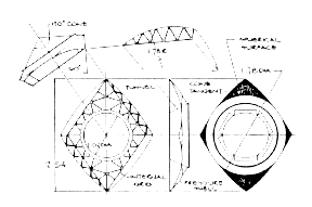
Fig.
15. Rhombic sub-module assembly.
Since the inner polygon is a
machined open grid lattice, it not only protects and supports these system runs
but allows access to them. Integral to these panels is a door jamb and sealing
surface. Twelve identical units like this form a 3.56 m diameter sealed ball.
The diameter selected is the minimum required to stow hatches between 1.02 m
openings without encroaching on them. For larger openings, proportionately
larger nodal balls are required, this enlargement being limited by the clearance
in the Shuttle payload bay.
Although it has not been indicated, a further
intention for adaptability, is some form of socket, stud or similar attachment
opportunity at each of the 14 "corners" of the structural ball. At these points,
inner and outer structures converge, offering locally high strength. While there
is no specific requirement for such provisions, the opportunity, if offered,
will almost certainly be used. If passed up, it will be difficult to add
later.
Since the lattice intersection must accommodate as many as 12
attached modules, nodes at the edges of any configuration offer many unoccupied
ports, usable for docking, EVA
or standard plug-in accessories like the
previously-shown propulsion and storage units, or tanks for consumables or
antennae. Any accessories, once developed, are directly transferable to another
port, another module or a different configuration.
It is obvious that an
adaptable nodal shell can be used in many ways. It could be a manned module for
a recovery repair and service vehicle. With nearly 11.5 m3 of volume inside the
inner polyhedron, it could be fitted for life support of a four man crew for ten
days to two weeks. Essentially the same vehicle can serve at a space base as a
rescue "lifeboat." Among the accessories that could be developed for this role
is a remote manipulator turret.
Figure 16 illustrates a proposed
docking/berthing interface for this system. The type developed for Apollo is
unsuitable because, projecting beyond the interface plane, it prevents lateral
approach; it fills the tunnel, requiring disassembly before use; and the mating
faces are different. The single-use Apollo/Soyuz device, although androgynous
(both sides identical), also projects awkwardly across the interface
plane.
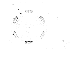
Fig. 16. Docking/berthing interface for lateral
assembly.
These precedents and the unique problems of this
closed system combine to define the docking requirements:
• Androgynous
(one system to develop)
• Flush faces for lateral engagement
• Positive
guidance for head-on encounter
• Light connection before pull-up
• Minimum
size and weight (many identical ports)
An added feature proposed for this
mechanism is retractability to move out of the way when a port is occupied by an
accessory module.
As a consequence the suggested method features inward
sloping triangular paddles, motor-driven through a range of positions
appropriate to each operational mode. With hooks at their ends, they also
perform the latching function by reaching through the opening in the opposing
interface and engaging sockets in the tunnel wall. When fully engaged and
locked, the paddles from both mating units lie inside the opposing tunnels,
leaving a clear passage available for immediate use. ,
For a typical
head-on docking the paddles are extended at an angle such as 45°. As the
interface planes near each other (approximately 25 mm short of complete closure),
a spring-loaded detent hook (not shown) prevents recoil while the paddles
further expand to engage. After the hooks enter sockets in the opposing tunnel
wall, a pull-up actuator in each paddle rigidises the connection.
As the
figure shows, the paddles can be positioned anywhere in a range exceeding 180°.
For lateral insertion into the structural stack, the paddles are flush with the
interface plane or below it. As soon as the mating units are approximately
aligned, the paddles extend to center the connection and continue to the engaged
position. When withdrawn completely into their own tunnel, the paddles and
latches are out of the way of an installed submodule whose attachment points can
be the six spots shown at the hinge ends.
The paddles are driven to any
commanded position by worm drive actuators located at the end of the hinges and
bussed together by a chain, perforated tape or similar drive girdling the
tunnel. Each actuator is indirectly connected to the paddle it drives by a
spring and damping system built into the base hinge.
All of the
mechanisms described and the dimensions assumed are tentative and subject to
revision as a result of further study or such approvals as will be required for
an international standard. Whatever develops will become an international
standard, one that is long overdue.
6. UNIVERSAL HABITABLE
MODULE
The habitable module required for most Space Station functions
seems to be close to the same length and diameter as the now-operational
Spacelab, but while Spacelab has been funded and developed, its design has been
concerned with a single unit (of variable length) compatible with the Shuttle
Orbiter payload bay. Little thought has been given to clustering multiple units
into space station assemblies; particularly, the end geometry does not lend
itself to assembly in any way but tandem. To a considerable extent, the thinking
applied to all previous manned vehicles has concentrated on making one unit
work. Much of this thinking can, it is hoped, be applied to the module
introduced in Fig. 17
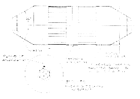
Fig. 17.
Universal habitable module.
Shaped for the tetrahedral truss
assembly method, this module has relatively long conical ends with converging
space which, if intelligently used for service functions, should be no
disadvantage. The module is envisaged as a stiffened shell with entry only at
the ends; any exposure or exit to the vacuum of space or to other modules is
through airlock nodes at the intersections. Except for circumferential bands
with thermal control shutters, it is completely covered with multilayer
insulation of any appropriate variety.
Since a leak-tight presurised
canister with this niuch volume, once built, should find many useful
applications, the structural shell has been designed to maximize adaptability
and usable volume. Typical shell construction for both cylindrical and conical
sections is shown in Fig. 18.
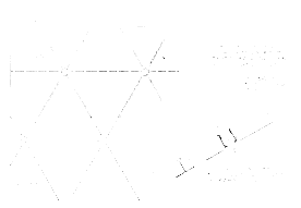
Fig. 18.
Integrally stiffened pressure shell with standard nodal attachment
provisions.
The integral external stiffening ribs form an
isogrid array of equilateral triangles with intersection nodes spaced about
180mm apart. The panels are machined from large aluminum alloy plates about 20
mm thick, leaving a skin of about 1.5 mm between ribs. Each nodal intersection
incorporates an outer socket and inner button for all thc attachments to the
shell. A suggested detachable captive collet fastener for all interior
attachments is shown in Fig. 19.
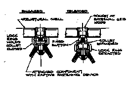
Fig. 19.
Standard captive collet fastener.
There are no frames in this
construction, not even where transportation trunnion fittings are attached.
Frames are avoided because these fittings introduce their loads into the shell
tangentially at patches with enough fasteners to match the load-carrying
capacity of the nodes. No additional shell reinforcement is expected, though it
can be provided if necessary by leaving enough extra material in the machined
plate. The trunnion fittings, needed only for transport, are removable, being
attached by the releasable fastener shown in Fig. 18.
The versatility of
this construction is further demonstrated by a standard window construction,
shown in Fig. 20. Instead of removing the whole shell area, only the skin
between stiffeners is cut out - in as many pockets as viewing requirements
dictate (16 in the example shown).
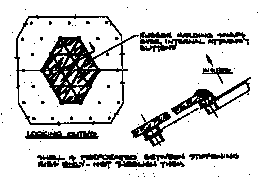
Fig. 20. Standard
window, exploiting attachment features.
The outer edge is sealed
by an elastomeric molding of appropriate cross section for window retention. Its
underside includes sockets that are retained by the ubiquitous internal buttons
around thc edge. Each of the buttons at nodes in the middle of the window also
retains an elastomeric supporting collar. This mid-panel support allows the
clear pane to be thinner.
Reinforcement to replace the skin removed for
vision can be an internal bonded doubler or enlargement of the local ribs if the
window location is known before the panel is machined. With the generous
structural margins expected for the pressure loads, no reinforcement may be
necessary.
This module is larger than those shown in most space station
design descriptions. However, having been sized by STS payload bay dimensions
and compatibility with the nodal ball, it should probably stay as it is. Any
extra volume is sure to be found useful after the start of service.
7.
CONSTRUCTION STRUTS AND NODES
As has been indicated in Fig. 11, there are
three combinations for struts bridging the node-to-node spacing. This is caused
by the different size of the two elements serving as nodes; pressurised balls
are significantly larger than strutconnecting "hedgehog" fittings. Where there
are no habitable modules, the nodal span is covered by two identical halfstruts.
Between nodal balls, if such a situation is realistic, two tripods are
appropriate.
When the gap between a "hedgehog" and a nodal ball is
filled, the two elements are combined. This means that the middle joint on a
tripod must be the same as that on a half-strut. In the nested strut system
proposed every two-element column can be made from elements of the kind
developed by the NASA Langley Research Center.
For the centre joint at
the large end of the strut, and in the corresponding position on a tripod, the
androgynous multi-fingered joint already developed should
be adequate,
although it may need an additional locking ring on each member to trap the
fingers so they cannot spread and release.
The small end androgynous
joint proposed here is again similar to the Langley design but secured by
external sleeves instead of an internal spring latch. It is shown in Fig. 21.
This is a well-known mechanism, generally secuted by a single outer sleeve.
However, since in an androgynous connection both sides must be identical, two
threaded sleeves are used.
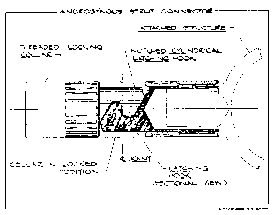
Fig. 21.
Androgynous strut end connector.
This choice offers a bonus:
the two can be tightened against each other to minimize play in the joint. Once
the ends are brought together by hand, advancement of the first collar holds the
assembly firmly enough to simplify operation of the second collar and subsequent
tightening.
The foldable tripod can be attached at three of the six
available spots on the docking interface. Since the space between two legs is as
wide as the access opening diameter, the port remains usable for EVA and the
legs themselves should be useful handholds.
Where construction struts
meet at a node, there is a "hedgehog" cluster fitting corresponding to an
airlock nodal ball. As illustrated in Fig. 22, the stubs project in the same
directions as elements emanating from ball nodes. The "12 o'clock" position at
the interface converges on the center of three-stub groups exactly in the same
manner as previously described for docking ports. The same numbering strategy
can also be employed here.
As with airlocks, a "hedgehog" is made
from identical stubs with rhombic bases. These bases, welded along their edges
form the same polyhedron. '
As the figure demonstrates, "hedgehog"
fittings attached to each other can, by themselves, make a double-faced truss
sandwich panel. With appropriate trunnion adaptors, the extended assembly should
serve well as a cradle for its own transportation to orbit; a pair of these
cradles could, between them, support their struts for the ride.
5.
CONCLUSIONS
The Space Station is a new and different type of program;
it will be a continuing process and not a one-off event. As such, it will demand
the characteristics offered by this construction system:
• An efficient
structural system which, because it uses the only stable polygon available, the
triangle, is inherently rigid; growth is not limited by low natural frequency.
• The adaptability that makes it rebuildable in another form.
•
Adaptability to accept a variety of plug in modules.
• The adaptability
offered by structure patterns that physically integrate the subsystems without
rework and without time-consuming argument and negotiation.
• The
adaptability inherent in structural frame consistency, the construction
struts and pressurized units conforming to the same lattice geometry - no extra
adapters.
• The economy offered by developing only six interchangeable
core construction units.
• The economy of identical interfaces and
identical
sub-units which, at an early stage, offer the cost benefits of
quantity.
While it is desirable to study and understand what a space
station must do, and, in the course of such study, to define what the starting
configuration should be, this system permits major changes of mind after first
service and for an indefinite period thereafter. In short, the development of
the elements can proceed without a definite configuration
decision.


 Fig. 1. The Skylab
Orbital Workshop, showing the grid floor.

 Fig.
4 . Approximations of an arbitrary shape with square and triangular
networks


 Fig 10. Tetrahedral
version of the "Delta".


